A cable tie that fails is annoying. A terminal that fails is a fire, a warranty claim, or a machine that stops mid-shift. Terminals and lugs are the smallest-value parts on the bill of materials and the ones that decide whether a connection survives ten years of vibration and thermal cycling. This guide walks through how ring, fork, pin, blade, butt and cord-end terminals are actually specified — connection type, wire range, stud size, insulation, crimp — and where the North American standards draw their boundaries.
Why the Termination Is Where the Run Fails
Study any field-return database and the pattern repeats: the wire is intact, the connector shell is intact, and the failure sits at the interface between conductor and terminal. There are three mechanisms, and all three are specification errors rather than manufacturing accidents:
- Wrong wire range. A terminal listed for 16–14 AWG does not develop its rated contact area on a 20 AWG conductor. The crimp looks acceptable because it holds mechanically, but the current-carrying cross-section is a fraction of design, and the joint runs hot.
- Wrong stud size. A ring that is too large for the stud does not sit flat under the nut. Contact becomes a line rather than a surface, and vibration works the joint loose.
- Wrong insulation for the environment. Vinyl insulation is the economical default, but it softens, embrittles and degrades where fuel, oil or sustained heat is present. Nylon costs marginally more and is the correct answer in engine compartments and industrial machinery.
None of the three is visible at installation. All three are eliminated at specification, which is the point of working family by family.
Step 1 — Pick the Terminal Family From the Connection, Not the Catalogue
The terminal family is dictated by how the connection is made and whether it will ever be disconnected. Work from the mating side backwards:
| Family | Mates with | Best for | Avoid when |
|---|---|---|---|
| Ring / circular terminals | Stud, screw or post with a nut | Permanent, high-vibration, high-current landings — earth bonding, motors, contactors, battery feeds | The joint must be disconnected without removing the fastener |
| Fork / spade terminals | Stud or screw, open side | Serviceable landings — loosening the screw is enough to slide the terminal free | Vibration is severe; a fork can creep out if the screw relaxes. Use a ring instead |
| Pin terminals | Spring or screw clamp, terminal block | Stranded wire entering a clamp where the strands would otherwise splay or shear | The block needs a ferrule-shaped (square) entry rather than a round pin |
| Blade / flat terminals | Push-on receptacle or clamp | Compact terminations on relays, switches and PCB-mounted blocks | Repeated mating cycles without a locking feature |
| Butt splices | Wire to wire, in line | Repairing or extending a run without a junction box | The splice must remain inspectable or re-openable |
| Insulated butt splices | Wire to wire, in line | Splices in damp or exposed locations where bare metal is not acceptable | Continuous flexing is expected — a splice is a rigid point, and the wire will fatigue beside it |
| Bullet connectors (male / female pair) | Matching bullet of the opposite sex | Reconnectable inline joints — lighting, sensors, accessories | Current is high; the contact area is small |
| Cord-end ferrules | Terminal block, screw or spring clamp | Stranded conductor entering any clamp, especially on CE/UL-inspected panels | Not applicable — this is the default choice, not the exception |
Two family decisions are worth calling out because they are commonly confused. First, ring versus fork is a serviceability decision, not a performance one: both can carry the same current, but only the fork can be removed without dropping the fastener, and only the ring is immune to creeping out of a relaxed joint. Second, spade and blade are not the same thing: the insulated quick-disconnect family is a push-on system with a matched receptacle, and its performance depends on the receptacle as much as the tab.
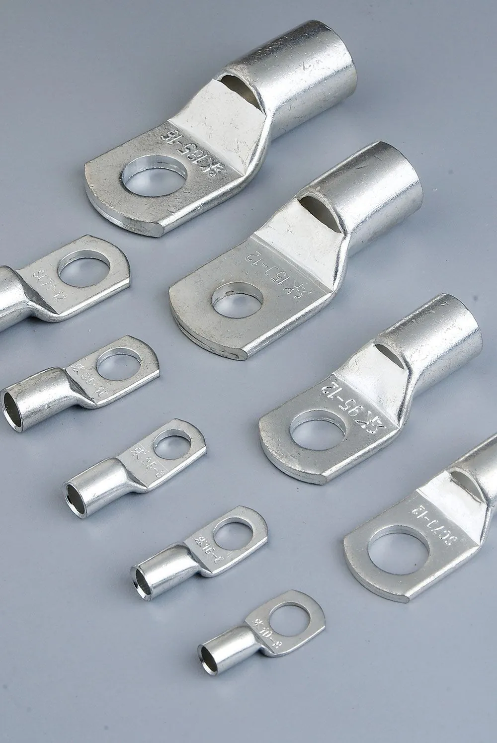
For heavier current, above roughly 10 mm², the ring family gives way to compression lugs. Our SC copper cable lugs are the tubed, hex-crimped construction used for battery and distribution cable, and they are specified by conductor cross-section plus stud diameter rather than by AWG.
Step 2 — Match the Terminal to the Wire, Using the Colour Code as a Cross-Check
Pre-insulated terminals carry a colour code that identifies the wire range they are built for. It is the fastest field check available, and it is standardised enough to rely on across suppliers:
| Insulation colour | Wire range (AWG) | Wire range (mm²) | Typical rating |
|---|---|---|---|
| Red | 22–16 AWG | 0.25–1.65 mm² | up to approx. 19 A |
| Blue | 16–14 AWG | 1.04–2.63 mm² | up to approx. 27 A |
| Yellow | 12–10 AWG | 2.63–6.64 mm² | up to approx. 48 A |
Three rules keep you out of trouble. The colour is a band, not a point — red covers a 6:1 range from 22 AWG to 16 AWG, so within the band the terminal is correct for all of it but not for a 14 AWG conductor. A terminal is rated for a range, never for a single size, so specifying "blue terminal" is complete only if the conductor sits inside that range. And the mm² figure on a European data sheet is the conductor cross-section, not the barrel bore — the two differ by roughly 10–15 %, which is exactly the margin that decides whether 1.5 mm² wire enters a 1.5 mm² barrel without strand damage.
When the same part is described in both systems, convert before comparing. The pairs you will meet most often: 0.75 mm² ≈ 18 AWG, 1.0 mm² ≈ 18 AWG, 1.5 mm² ≈ 16 AWG, 2.5 mm² ≈ 14 AWG, 4.0 mm² ≈ 12 AWG, 6.0 mm² ≈ 10 AWG, 10 mm² ≈ 8 AWG, 16 mm² ≈ 6 AWG.
Step 3 — Size the Ring to the Stud, Not to the Cable
Ring and fork terminals have two independent sizes: the wire barrel and the stud hole. Getting the wire right and the stud wrong is one of the most common specification slips, because the stud size is set by the equipment, not by the cable. Stud sizes are still quoted in the imperial number series for small fasteners:
| Stud size | Major diameter (inch) | Major diameter (mm) | Typical uses |
|---|---|---|---|
| #4 | 0.112" | 2.84 mm | Control panels, small relays, PCB blocks |
| #6 | 0.138" | 3.51 mm | Instrumentation, terminations, light-duty earth |
| #8 | 0.164" | 4.17 mm | General panel wiring, contactor coils |
| #10 | 0.190" | 4.83 mm | General power terminations, fuse holders |
| 1/4" | 0.250" | 6.35 mm | Motors, battery feeds, larger contactors |
| 5/16" | 0.312" | 7.92 mm | Automotive and machinery power landings |
| 3/8" | 0.375" | 9.53 mm | Heavy power, alternator and starter cable |
| 1/2" | 0.500" | 12.7 mm | High-current battery and distribution cable |
The practical rule: the stud should fill the ring comfortably, with the ring seating flat on the landing. A ring markedly larger than the stud is not a substitute for the right part — it reduces the contact area, and it will not centre under the washer. When the stud is metric, the millimetre column is what you match to; an M4 stud takes a 4.2–4.5 mm ring, not a #8 (4.17 mm) by coincidence.
Step 4 — Insulated or Non-Insulated: A Voltage and Environment Question
The choice is not decorative. It is set by voltage, location and whether the joint is exposed.
| Non-insulated | Pre-insulated (vinyl) | Pre-insulated (nylon) | |
|---|---|---|---|
| Temperature | Metal only — limited by the plating | approx. –10 °C to +75 / +105 °C depending on grade | up to approx. +105 °C, higher-grade types to +150 °C |
| Short-circuit protection | None — adjacent terminals can touch | Yes; barrel insulation prevents flashover | Yes |
| Oil, fuel, chemical | Not applicable | Poor to moderate | Good — the reason nylon dominates automotive and engine-bay work |
| Strain relief | None on its own | Limited; sleeve supports the wire | Better; the extended sleeve and metal grip support the insulation |
| Best for | Tight, well-separated panels; high-temperature areas where plastic would degrade; crimp-and-heat-shrink builds | General-purpose wiring, cabinets, appliances, dry indoor locations | Automotive, machinery, vibration and chemical exposure |
Where a joint must be both insulated and sealed against moisture, the correct construction is a non-insulated or crimp terminal followed by adhesive-lined heat-shrink tubing, not a thicker layer of vinyl. Vinyl is not a moisture barrier, and a splice that has to survive wet locations needs the adhesive seal that only heat-shrink provides.
Step 5 — Cord-End Ferrules: The One Component That Is Not Optional
If stranded wire enters a screw or spring clamp, it should enter through a ferrule. This is the single most consistently enforced point in European and North American panel inspection, and for a mechanical reason: a bare stranded conductor deforms under the clamp screw. Strands splay, some break, the effective cross-section falls, and the joint relaxes over thermal cycles. A ferrule turns the stranded end into a solid, square-profiled pin sized to the clamp.
Ferrules are specified by two standards families that buyers frequently mix up:
| DIN 46228 (Europe) | UL 486F / CSA C22.2 No.291 (North America) | |
|---|---|---|
| Bare (no sleeve) | DIN 46228-1 | UL 486F-A |
| Insulated (plastic sleeve) | DIN 46228-4 | UL 486F-E |
| Twin / double | DIN 46228-1 / -4 (twin variant) | UL 486F (twin defined) |
| Cross-section range | 0.5–50 mm² | 1/0–20 AWG stranded copper (per scope) |
The DIN 46228-4 collar colour identifies the conductor cross-section so an inspector can verify the gauge at a glance:
| Cross-section | AWG approx. | Collar colour (DIN 46228-4) |
|---|---|---|
| 0.5 mm² | 20 AWG | White |
| 0.75 mm² | 18 AWG | Grey |
| 1.0 mm² | 18 AWG | Red |
| 1.5 mm² | 16 AWG | Black |
| 2.5 mm² | 14 AWG | Blue |
| 4.0 mm² | 12 AWG | Grey |
| 6.0 mm² | 10 AWG | Yellow |
| 10 mm² | 8 AWG | Red |
| 16 mm² | 6 AWG | Blue |
Note the trap: DIN reuses colours across sizes — grey appears at both 0.75 mm² and 4.0 mm², blue at both 2.5 mm² and 16 mm². The number printed on the collar is authoritative; the colour is a convenience. Also note that the French standard NF C 63-023 assigns different colours for some sizes, so a ferrule bought against a French colour chart will not match a German one. Confirm against the manufacturer's chart before you put a colour in a specification.
Two configurations round out the family. Twin (double) ferrules place two conductors in a single clamp slot — they are a purpose-built sleeve, not two singles side by side, and the collar is marked for the per-conductor size (a blue "2×2.5" takes two 2.5 mm² conductors, not 5 mm²). If the same wire has to land in two separate clamp positions, the correct part is a non-insulated cord-end terminal or a bridging terminal block, not a twin.
Step 6 — The Crimp Is Half the Component
A terminal only reaches its rated performance through a correct crimp. Specifying a good terminal and crimping it with the wrong die is a common way to fail an audit while holding a compliant part number. The control points:
- Strip length matches the barrel: long enough to fill it, short enough that no bare conductor protrudes behind the insulation grip. Over-stripping is the most common defect found in incoming inspection.
- Correct die nest for the terminal and wire combination. Insulated terminals need an insulated-terminal die (which crimps barrel and sleeve without cutting the sleeve); non-insulated terminals need a bare-terminal die. A single "universal" crimper is a compromise, not a substitute.
- Crimp geometry — a uniform indent or hex profile with no barrel cracks and no partial compressions. On production lines, crimp height is controlled as a process parameter with a defined window rather than accepted on visual inspection alone.
- Pull test on a sample per batch, tied to the terminal and wire revision actually in use. A joint that fails a pull test has failed regardless of how it looks.
- Torque at the landing. The crimp is only half the joint; the screw or nut side has its own torque specification, and under-torquing is what allows a correct crimp to loosen.
Soldering is not a substitute here. In a screw-clamp application a tinned or soldered end cold-flows under the clamp and relaxes, which the relevant product standards treat as non-compliant rather than merely inferior. Solder a stranded end only where the connection is a fixed solder joint by design.
Step 7 — Know Which Standard Covers Which Product
Terminals and ferrules are covered by different standards, and the boundary is not intuitive. Getting it wrong at specification stage is how a project ends up with parts that are compliant in principle but not covered by the standard the inspector is reading.
| Product | North American standard | Notes |
|---|---|---|
| Ring, fork, pin, blade and butt-splice terminals; pressure wire connectors | UL 486A-486B / CSA C22.2 No.65 / NMX-J-543-ANCE | A trinational harmonised standard; current editions are UL 486A-486B 4th edition and CSA C22.2 No.65:25. Covers copper 30 AWG (0.05 mm²) to 2000 kcmil (1010 mm²) and aluminium from 12 AWG, with temperature rise limited to the conductor insulation rating (75 °C or 90 °C). |
| Bare and covered ferrules, 1/0–20 AWG stranded copper | UL 486F / CSA C22.2 No.291 | Ferrules were moved out of the wire-connector scope and are now evaluated under their own standard, together with the crimping tool system. |
| Twist-on / screw-on splicing connectors (wire nuts) | UL 486C / CSA C22.2 No.188 | A separate scope again — covered in our UL 486C wire nut guide. |
| Cable ties | UL 62275 / CSA C22.2 No.62275 | See our UL 62275 vs IEC 62275 comparison. |
Two exclusions in the UL 486A-486B scope catch buyers out. Insulated connectors above 2000 V are outside it, and so are flat quick-connect terminals and wire-binding screw terminals — the push-on blade family is covered by other requirements, which is why a supplier claiming blanket UL 486A-486B coverage for an entire quick-disconnect range deserves a question. The other one to remember is that manual twist-on connectors sit in UL 486C, not UL 486A-486B.
Specification Checklist for Terminals and Lugs
- Connection method first — ring for permanent and vibration, fork for serviceable, pin or ferrule for clamps, butt or bullet for inline joints.
- Wire range — confirm the actual conductor size in mm² and AWG, and check the terminal's rated band covers it, not just the colour.
- Stud size — match the ring bore to the fastener diameter, in millimetres if the stud is metric.
- Current — above roughly 10 mm² move from ring terminals to compression lugs sized by cross-section.
- Insulation — vinyl for dry indoor duty, nylon where heat, oil, fuel or vibration is present, heat-shrink where moisture sealing is required.
- Ferrules — mandatory for stranded wire in screw or spring clamps; size by conductor cross-section, specify DIN 46228-4 or UL 486F explicitly, and confirm colour against the manufacturer's chart.
- Crimp system — the tool and die must be specified with the terminal, and inspection must include pull-test evidence tied to the terminal revision.
- Standard coverage — name the standard and edition for each product family on the purchase order, and ask for the certificate's scope rather than the cover page.
Sourcing Terminals, Lugs and Cord-End Ferrules
Our terminals and wiring accessories range covers ring, fork, pin and blade terminals in insulated and non-insulated versions, butt splices, bullet and spade connectors, twin and single cord-end ferrules, SC copper cable lugs and terminal blocks — supplied from a factory operating ISO 9001, ISO 14001, ISO 45001 and IATF 16949 management systems, documented on our certifications page. Tell us the conductor size, the stud or clamp the wire lands in, the environment and the standard you are inspecting against, and we will confirm the right part, provide samples for crimp validation, and quote for OEM or private-label supply. Custom terminal dimensions, plating and packaging are available through our OEM programme.