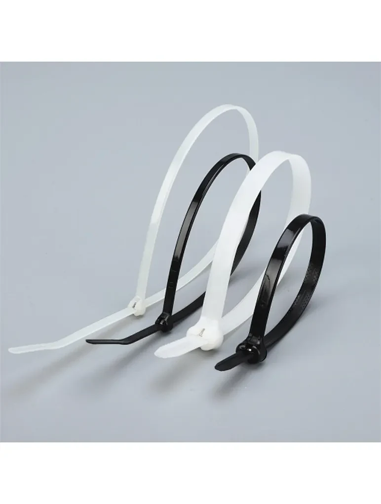
An EV charging station is one of the harshest environments a cable tie will ever see: continuous sunlight, rain and temperature cycling on the outside; vibration, high current and a flame-retardant requirement on the inside; and a heavy, repeatedly flexed charging cable hanging off it. Yet cable ties are usually the last item specified and the first to fail. This guide covers what the relevant standards actually require, where ties are used on a charging installation, and what to specify at each point.
Why EV Charging Is Harder Than Ordinary Outdoor Electrical Work
A pole-mounted charger combines several conditions that are individually manageable but punishing together:
- Permanent UV exposure. Not seasonal — the enclosure, the cable support and the ties are in direct sun for a decade or more.
- Wet and freezing cycles. Water ingress followed by frost cycling embrittles inadequate plastics and works fasteners loose.
- Vibration. Traffic, contactor switching, and cable handling transmit continuous low-amplitude vibration into every fastener.
- Repeated flex and abrasion. The charging cable is dragged, coiled and hung thousands of times over its life. Ties routed against it must not cut the jacket.
- Electrical safety. Charging equipment operates at high voltage and continuous load, so anything non-metallic inside the enclosure has to meet a flammability rating.
What the Standards Say
Cable ties are not themselves "EVSE", so the standards address them indirectly — through cable management, flammability, and environmental requirements on the equipment. The provisions that matter to a tie specification are:
| Standard | Provision relevant to cable management |
|---|---|
| NEC Article 625 (625.17(B)/(C)) | Charging cables are limited to 25 ft (7.5 m); where a longer reach is required, an approved cable management system must be provided — ties and supports are part of that system. |
| UL 2594 (3rd edition, 2022) | Input range extended to 1000 V AC; CCID personnel protection required; enhanced UV, chemical and water exposure testing for outdoor equipment. Cable length may exceed 7.5 m with a cable management system. |
| UL 2231 | Personnel protection systems for EV supply circuits — CCID and grounding monitoring. |
| IEC 61851-1 | Addresses "cable management and storage means for cable assemblies" and strain relief for charging cables. |
| CSA C22.2 No. 280 | Tri-national (CSA / UL / ANCE) EVSE standard for lower-power equipment. |
| SAE J1772 / J3400 | Connector and cable assembly requirements the installation must accommodate. |
The practical translation: the cable management system is a code item, not an accessory. And because the equipment must pass UV, chemical and water exposure testing, components in contact with the cable and enclosure are held to a similar environmental standard.
Three Locations, Three Different Ties
Treat a charging installation as three separate specification zones. Using one tie type across all three is the most common mistake.
Zone A — Inside the enclosure (control board, harness, contactors)
Requirements: UL94 V-0 flame retardancy, continuous temperature typically to +105°C, non-conductive, and small sizes suitable for control wiring.
Specify flame-retardant V-0 nylon ties in miniature and standard sizes, and heat-stabilized grades near power stages and contactors. Where the design includes power electronics running hotter, PA46 ties rated to +150°C cover the high-temperature corner.
Zone B — Exterior cable support, cabinet interior-to-pole routing
Requirements: UV-stabilized black nylon (−40°C to +105°C), good vibration resistance, and head designs that do not snag or cut.
Specify UV-resistant black ties, and prefer low-profile or outside-serrated designs where the tie sits against cable insulation. Use tie mounts or wire saddles to route along the pole or cabinet wall — saddles hold without crushing the jacket, which matters on a cable that will be flexed for years.
Zone C — Heavy charging cable, hanger points, pedestal hardware
Requirements: high tensile strength, high security, resistance to UV and salt if the site is coastal or treated with de-icing salt.
Specify 304/316 stainless steel ties for structural fixing, or coated steel-barb ties where the tie contacts the cable jacket — the nylon coating prevents a steel edge from sawing into the insulation under vibration.
Specification Table
| Location | Critical requirement | Recommended tie |
|---|---|---|
| Control board, low-voltage wiring | UL94 V-0, non-conductive | Flame-retardant V-0 nylon, miniature/standard |
| Near contactors, power stage | +105°C to +150°C continuous, V-0 | Heat-stabilized or PA46 ties |
| Cabinet exterior, cable guidance | UV-stable, −40°C/+105°C, no abrasion | Black UV nylon, outside-serrated / low-profile |
| Routing along pole or wall | Secure without crushing the jacket | Wire saddles, screw or adhesive tie mounts |
| Cable hanger / strain relief | High tensile, long service life | Stainless steel (coated) or coated steel-barb |
| Coastal / de-icing salt sites | Chloride resistance | 316 stainless steel |
| Enclosure in public space | No sharp edges, tamper resistance | Low-profile head ties; security seals where required |
Six Mistakes That Show Up in Field Failures
- Natural (white) nylon used outdoors. It embrittles within a season. Every exterior tie must be black UV-stabilized — without exception.
- Ordinary ties used inside a V-0 enclosure. If the enclosure specification calls for V-0 internal materials, standard nylon is a non-conformance waiting to be raised.
- Bare stainless steel cinched onto a flexible cable. Under vibration, the steel edge cuts the jacket. Use a coated steel-barb tie, or a saddle that spreads the load.
- Over-tensioning. A tie is a fastener, not a clamp. Tightening until the cable deforms creates a stress point that fails in fatigue.
- No allowance for thermal movement. Cable expands and contracts; a tie that leaves no slack becomes the anchor point of a pulling load.
- Ignoring the site chemistry. Coastal sites and winter de-icing salt both supply chlorides — the condition where 304 stainless will pit and 316 will not.
Installation Notes
- Cut tails flush and orient the cut away from hands and cable. A protruding tail is an abrasion tool.
- Space ties evenly and use two ties per direction change so that no single tie carries the full load of the cable's mass.
- Where the cable hangs unsupported for more than 25 ft (7.5 m) — including the reach from the cabinet to the vehicle — the installation needs a cable management system, not just ties. Ties support; they do not tension.
- Keep the DC/power cable and the communication cable on separate routing where practical to avoid noise coupling.
Where Cable Ties Sit in an EV Programme
Ties are a few cents on a charging-station bill of materials, and a disproportionate share of field service visits. The specification work is genuinely small: decide UV-stable black for anything outdoors, V-0 for anything inside the enclosure, and coated steel or 316 for structural and coastal fixing.
We manufacture the full set — V-0 flame-retardant ties, heat-stabilized and PA46 high-temperature ties, UV black nylon ties, 304/316 stainless steel ties and coated steel-barb ties — with our nylon range certified to UL 62275 (File E220676, Type 21). For automotive-grade programmes we work to IATF 16949 with PPAP documentation.
Send us your application — indoor or outdoor, enclosure flammability requirement, cable weight and site environment — and we will confirm the specification and ship samples.