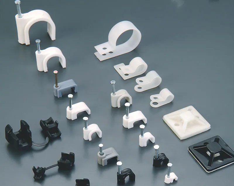
Cable ties get the attention, but on most cable runs it is the fixing that fails first. A clip that is too small pinches the insulation, a nail clip that is too large lets a coaxial cable drift and lose signal, an adhesive mount that was never meant for a hot engine bay lets go in a month, and a cable gland with the wrong thread type strips its way into a hole that no longer seals. This guide covers how clips, clamps and glands are actually specified — fixing method, size, material and thread — so the run you buy for is still intact in five years.
Why the Fixing Decides Whether the Run Survives
A cable fixing carries three jobs at once: it holds the cable, it protects it from abrasion and strain, and — in the case of glands and sealed mounts — it keeps water and dust out of an enclosure. Every failure mode follows from getting one of those wrong. The three most common ones we see in field returns and site audits:
- Over-compression. A clip sized below the cable's outer diameter (OD) compresses the jacket and insulation. On signal cable this changes impedance; on power cable it creates a long-term fault point.
- Under-support. A clip sized above the cable OD does not grip. Vibration works the cable loose, and the run migrates along the surface until it fouls something.
- Environment mismatch. Standard PVC fixings embrittle under UV in one to three years, and most pressure-sensitive adhesives soften above roughly 60 °C while the clip itself may be rated higher.
None of these show up at installation. They show up in a warranty claim or a failed inspection, which is why fixings deserve the same specification discipline as the cable itself.
Step 1 — Match the Fixing Method to the Surface
The fixing method is decided by what you are mounting to and whether the run is permanent. This is the first fork in the selection process:
| Fixing type | How it mounts | Best for | Watch out for |
|---|---|---|---|
| Nail-in clips (round / coaxial) | Pre-installed hardened steel nail, one-piece | Flat and round cable along wood, masonry and baseboards — coaxial, Cat5e/6, telephone, alarm | Non-adjustable once driven; sizing must be exact or the cable is pinched and signal degrades |
| Adhesive clips and mounts | Foam or acrylic tape backing, tool-free | Light-duty runs on smooth, clean, hard surfaces — panels, cabinets, desks, low-voltage data | Surface preparation is everything; load capacity is limited and largely set by the adhesive, not the plastic |
| Screw-mount R-type clamps | Single screw through the clamp body | Permanent runs at 6–23 mm cable OD; the workhorse for harness, panel and conduit support | Leaves a hole; over-tightening distorts the clamp and reduces grip |
| Saddles and two-hole straps | Two mounting holes, low profile | Heavy cable, conduit and rigid runs needing real holding power | Needs a solid substrate — at least one screw into a stud on drywall |
| Tie mounts | Adhesive base plus screw hole, takes a cable tie | Bundles of mixed sizes; the tie, not the base, sets the bundle diameter | Not for heavy cable or high-temperature surfaces |
For flat cable, use a flat profile clip; for round cable and bundled runs, a round or circle clip. Coaxial clips look similar to round clips but are sized around the tighter tolerances of RF cable — substituting a generic round clip is a common and costly mistake on RF and video runs.
Step 2 — Size the Clip to the Cable OD
Cable clip sizes are stated as the internal diameter of the clip opening, and that should match the outer diameter of the cable — not the conductor size, and not the bundle diameter if you are clipping a single cable. Typical pairings:
| Cable type | Typical cable OD | Clip opening to specify |
|---|---|---|
| USB / small data | 3–4 mm | 4–5 mm |
| Telephone / alarm | 4–6 mm | 5–6 mm |
| Cat5e / Cat6 network | 5–6 mm | 6–7 mm |
| Coaxial / RG6 | 7–8 mm | 7–8 mm |
| Twin-and-earth, small power | 7–11 mm | 8–12 mm |
| Armoured / heavy multi-core | 12–40 mm | Match OD; use steel, saddle or R-clamp |
Two rules that prevent most sizing errors: when in doubt, go one size up rather than down (an oversized clip is a loose hold, an undersized clip is damaged cable), and measure the actual cable rather than trusting a nominal figure — jacket thickness varies enough between suppliers to move you a size.
Step 3 — Choose the Material for the Environment
Material sets the temperature range, the UV life and the chemical resistance, and it is the single biggest driver of long-term cost of ownership:
| Material | Service temperature | UV / outdoor | Typical use |
|---|---|---|---|
| PVC | approx. –10 °C to +60 °C | Poor — degrades outdoors | Indoor, light duty, lowest cost |
| Nylon (PA66) | approx. –40 °C to +85/100 °C depending on grade | Good when UV-stabilised (black grades) | Indoor and outdoor industrial, panels, harnesses, automotive |
| Stainless steel / plated steel | –60 °C to +300 °C and above | Excellent (SS316 for coastal and marine) | Heavy cable, conduit, high-temperature and marine |
If a run is outdoors or in a vehicle, specify a UV-stabilised nylon grade rather than a natural (unpigmented) clip — the black UV-stabilised compounds are formulated for exactly this, and a natural clip exposed to sunlight is the most common premature failure we are asked about. For anything within reach of salt spray, go stainless.
Step 4 — PG vs Metric Cable Glands: The Specification Trap
If your run enters an enclosure, junction box or machine panel through a gland, thread type is a hard specification — and the two dominant systems are not interchangeable, even where the sizes look close.
| Metric (M thread) | PG thread | |
|---|---|---|
| Standard | ISO metric conduit thread, EN 60423 | DIN 40430 (Stahlpanzerrohrgewinde / Panzergewinde) |
| Thread angle | 60° | 80° — coarser and shallower |
| Size notation | M12, M16, M20, M25, M32 (outer diameter in mm) | PG7, PG9, PG11, PG13.5, PG16, PG21, PG29 |
| Status | Current global standard | Retracted standard; maintained for legacy equipment |
| Where you meet it | New panels, automation, EV charging, solar, renewables | Older European machinery, sensors, retrofit and MRO |
Two practical consequences:
- Do not force a metric gland into a PG hole, or the reverse. The 60° and 80° profiles do not mate. Forcing the thread strips the entry, and once the thread form is damaged the IP rating of the enclosure is gone — the seal depends on correct thread engagement, not on how tight the nut feels.
- The PG number is not a diameter. A PG nominal size approximately corresponds to the maximum cable diameter the conduit can pass — which is why PG13.5 exists at all. Sizing a PG gland by assuming "PG13.5 ≈ 13.5 mm" leads to the wrong part.
The good news for upgrades: adapters and reducers (for example PG16 male to M20 female, or a PG-to-metric reducer) let you seat a modern gland in an existing legacy hole without re-tapping or drilling. That is standard practice in retrofit work.
Selection rule of thumb: new designs — always metric, because it is the current standard and gives you the tighter size steps and sealing tolerance that come with a fine thread. Legacy equipment — match what is already tapped. If you are supplying a machine builder, ask which thread the customer's panel is tapped for before quoting; it is far cheaper than shipping a second batch of glands. Our metric thread cable glands and PG thread cable glands cover both systems, so a mixed project can ship from one source.
Step 5 — Make Adhesive Fixings Actually Hold
Adhesive mounts fail for a reason that has nothing to do with the clip: substrate preparation. If you are specifying self-adhesive clamps or adhesive tie mounts, include the installation method in the specification, because the fix is procedural:
- Clean the surface with isopropyl alcohol to remove oil, dust and mould release — on a smooth, hard substrate only (laminate, metal, glass, sealed paint). Adhesive is not a solution for rough or porous surfaces.
- Press and hold for 20–30 seconds, then let the bond cure before loading it — most pressure-sensitive adhesives reach working strength over hours, not seconds. Loading immediately is the single most common cause of fall-off.
- Respect the temperature window. Cold surfaces weaken the bond and hot surfaces soften it; where either applies, specify a mechanical fixing instead.
Where a run is permanent, heavy or vibration-exposed, do not rely on adhesive at all: use a screw-mount clamp, a saddle, or a mount with a screw hole as mechanical backup. And where the cable is bundled rather than single, pair the fixing with a tie — our cable tie range covers the UV-stabilised and heat-stabilised grades that suit outdoor and elevated-temperature runs.
Fixings Specification Checklist
- Surface and permanence — smooth and temporary points to adhesive; rough, permanent or load-bearing points to screw or nail fixing.
- Measure the cable OD and specify the clip by opening diameter; when in doubt, one size up.
- Environment — outdoor or UV exposure means UV-stabilised nylon or steel; high temperature means steel or a high-temp polymer, and an adhesive review.
- Load — single cable or bundle? Bundles need a mount plus a tie, not a single clip.
- Thread type for any enclosure entry — metric for new builds, PG for legacy, and adapters where the two must meet.
- Installation method — write the cleaning, pressing and cure steps into the spec if adhesive is used.
Sourcing Cable Fixings Without the Guesswork
Cable clips, clamps and glands are low-value parts that cause a disproportionate share of installation problems, so the cheapest quote is rarely the cheapest outcome. Our cable clips and wire clamps range covers round and flat clips, coaxial clips, R-type clamps, saddles, adhesives and tie mounts, alongside both metric and PG cable glands — from a factory with ISO 9001, ISO 14001, ISO 45001 and IATF 16949 management systems, documented on our certifications page. Tell us the cable type and OD, the mounting surface, the environment and — for glands — the thread on the customer's panel, and we will confirm the right part, provide samples for fit check, and quote for OEM or private-label supply.